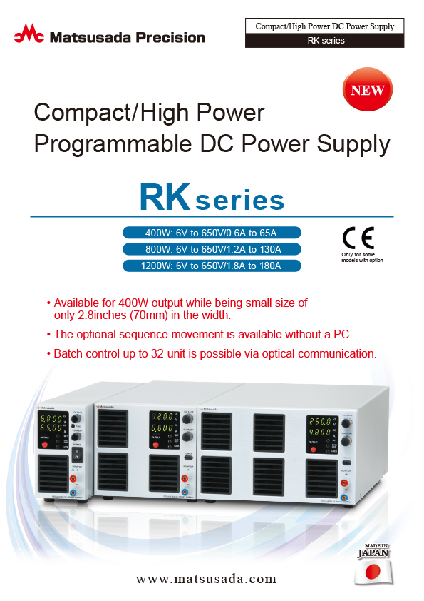
Compact / High Power Programmable DC Power Supply
- Voltage range: 6V to 800V
- Current: 0.6A to 180A
- Power: 385 to 1200W
- Multiple functions

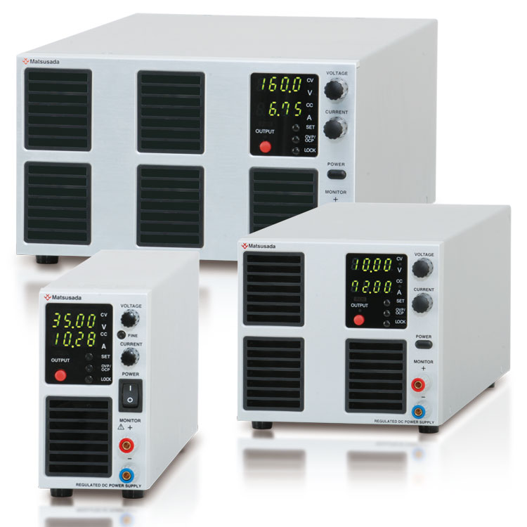
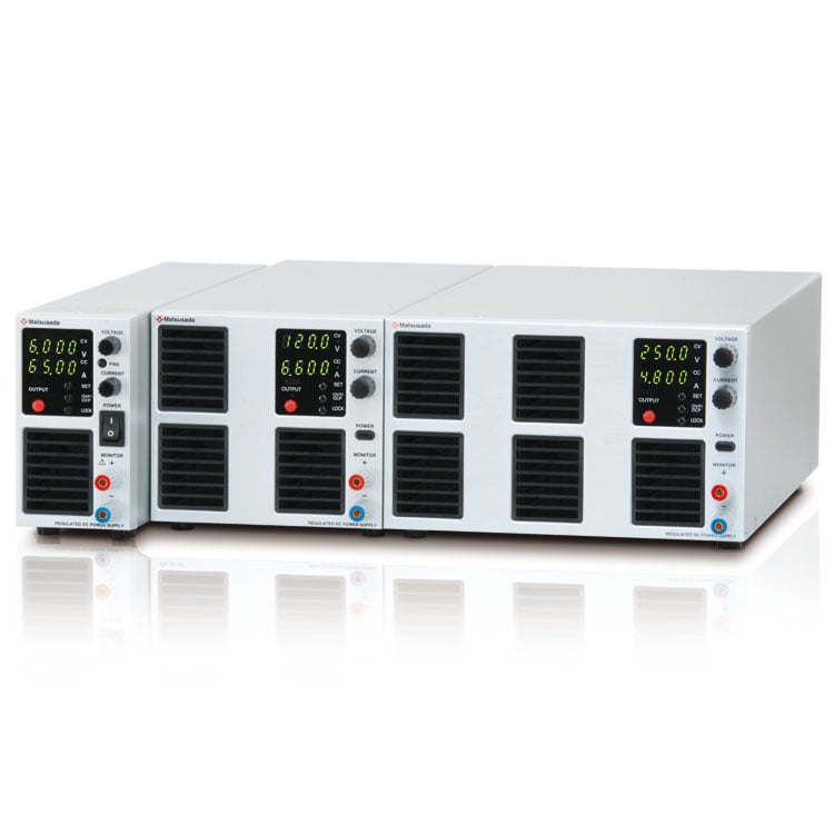
A 2.76 inches (70 mm) wide, this 400 W compact size
Low noise, multiple functions, and digital communication are highlights of supply which can be used from R&D to a variety of applications. All this convenience in a small DC power supply.
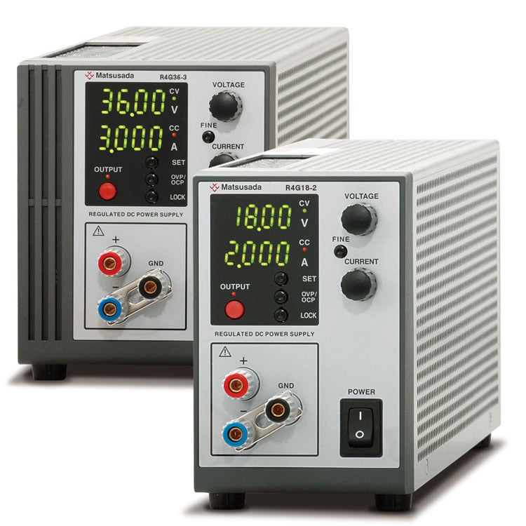
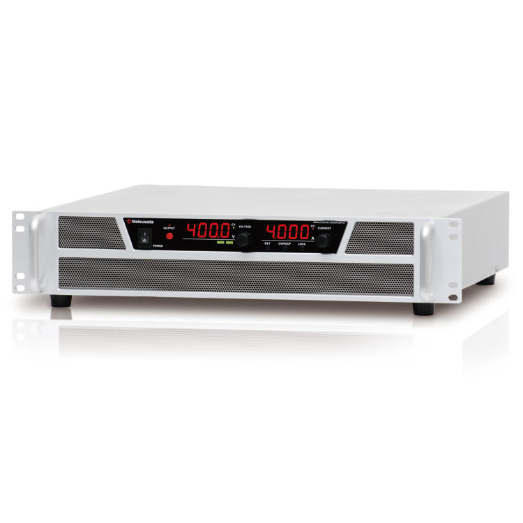
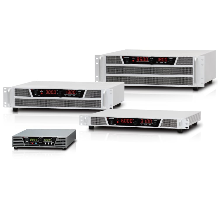
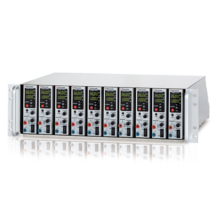
RK series is a small, programmable desktop 400 W, 800 W, 1200 W high output power supply.
Our low noise switching method includes several features such as a Delay trigger, Memory function, and Two-mode lock
function to prevent operator mistakes. All this enables the user to operate the supply for a wide range of applications.
Moreover, the sequence function enables the user to control the supply without a laptop.
The digital interface is also standard, with LAN, USB, RS-232C, RS-485, or GPIB control, allowing the operator to use the system in many different production environments.*
(Only for some models with option are applied to CE.)
* Adaptors or options will be needed additionally.
Features and Benefits
- Compact and high power 400 W, 800 W, 1200 W
- Ideal for research and development with low noise switching method.
- PFC circuit and universal input would not select the place of operation.
- Various operations by connecting multiple power supplies, such as master/slave, are possible.
- The sink current suppression is used to reduce the reverse current flowing from the load to the unit in order to prevent a voltage drop on the load as the output is OFF or the set voltage is lowered.
- Operability and safety are improved with new features of the Two-mode lock function and acceleration rotary encoder, which accelerate the output ramp-up with the speed of rotating the encoder.
Sink Current Suppression
RK series featured function to sink current, and enables to decrease the voltage quickly when turning off the output or when controlling the voltage down, which increases the safety of operation. In the case of continuous aging tests in short intervals, quick voltage fall time increases the efficiency of the process. On the contrary by using sink current prevention function, it is possible to prevent voltage drop on the load by decreasing the current flow from the load to the power supply when turning off the power supply or when decreasing the output voltage.
Note: It is not possible to stabilize the output by controlling the back current. In case of load which has inverse voltage or over rated voltage, such as inductive load or regenerative motor, protect the power supply by adding a dummy resister or diode to prevent back current.

Multi Setting Function
Function to memorize three different voltage and current settings in addition to the standard preset function. No need to adjust the output when different settings, and convenient function for production inspection process or testing which require frequent data taking.

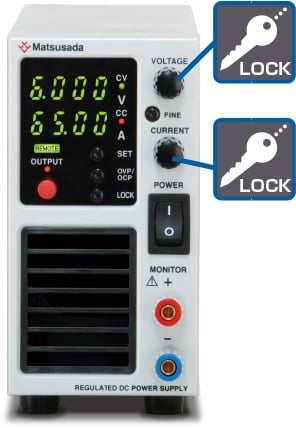
Two-mode Lock Function
Function to select two different lock functions for two different purposes. "Full Lock" locks all the functions on the front panel, and "Normal Lock" locks all the functions except for ON/OFF. "Full Lock" mode shall be good in case misoperation has to be completely avoided, and "Normal Lock" mode shall be good in case to avoid misoperation but secure the way for emergency stop of the power supply. You can select the best mode according to your level of "Security".
(Each modes, emergency stop is possible with Power Switch.)
Full LOCK
Lock all the functions other than reset lock mode, and effective for the purpose to avoid misoperation when controlled
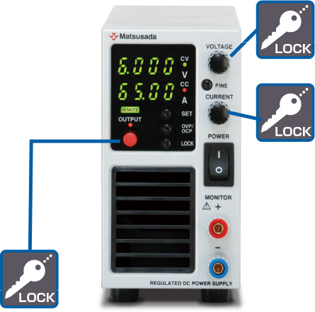
Normal LOCK
Lock voltage and current setting dial, and effective for the purpose to avoid changing output setting by mistake or when an easy emergency stop is required.
Delay Trigger Function
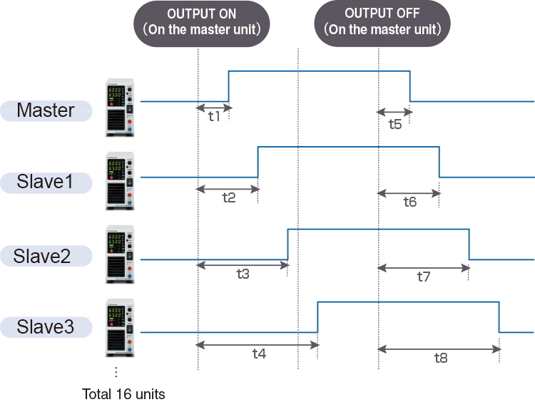
* t1 to t 8 can be set in the range 0.0 s to 99.9 s.
This function enables the power supply to be set to delay the output trigger timing. Either in the case of a single unit of RK series power supply or in case of multiple power supplies in Master/Slave connection *1, it is possible to use this feature among multiple DC power supplies *2 having individually different output voltage/current setting *3
- Can be connected up to 16 pieces.
- R4K-36 series, R4K-80 series, RK-80 series, RKT series, TB series and REK series. Detail datasheet for each model is available. Please contact the nearby sales office.
- Only for slave-local. In the case of slave remote control, exact same model of power supply needs to be used. Also, in the case of slave-local, each output voltage and current can be set individually. In the case of slave-remote, output voltage, and current can be set with a one-control function in which each slave unit follows the master unit setting.
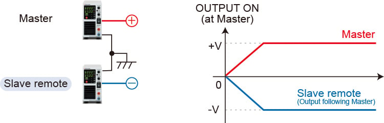
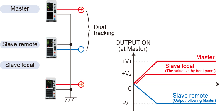
Dual Tracking, Multiple Outputs
Dual tracking control, which enables both positive and negative outputs simultaneously in master-slave operation, is possible. Multi outputs and various versatile operations are also possible by combining above dual tracking control and slave local mode. Positive and negative output (+V, -V) of dual tracking control and set output voltage of slave local mode can be output simultaneously by turning on the master unit.
Dual tracking
Multiple outputs
Models
 : They are the models which can correspond to CE marking with -LCe option.
| Model | Output | Ripple (rms) | Safety standards | ||||
|---|---|---|---|---|---|---|---|
| Voltage [V] | Current [A] | Power [W] | Voltage | Current *1 | |||
| RK6-65 | 0 to 6 V | 0 to 65 A | 390 W | 8 mV | 130 mA | ||
| RK6-130 | 0 to 130 A | 780 W | 8 mV | 260 mA | |||
| RK6-180 | 0 to 180 A | 1080 W | 15 mV | 360 mA | |||
| RK10-40 | 0 to 10 V | 0 to 40 A | 400 W | 10 mV | 80 mA | ||
| RK10-80 | 0 to 80 A | 800 W | 10 mV | 160 mA | |||
| RK10-120 | 0 to 120 A | 1200 W | 15 mV | 240 mA | |||
| RK15-26 | 0 to 15 V | 0 to 26 A | 390 W | 10 mV | 60 mA | ||
| RK15-54 | 0 to 54 A | 810 W | 10 mV | 110 mA | |||
| RK15-80 | 0 to 80 A | 1200 W | 15 mV | 160 mA | |||
| RK20-20 | 0 to 20 V | 0 to 20 A | 400 W | 8 mV | 32 mA | ||
| RK20-40 | 0 to 40 A | 800 W | 8 mV | 70 mA | |||
| RK20-60 | 0 to 60 A | 1200 W | 15 mV | 96 mA | |||
| RK30-13 | 0 to 30 V | 0 to 13 A | 390 W | 4 mV | 10 mA | ||
| RK30-27 | 0 to 27 A | 810 W | 6 mV | 25 mA | |
||
| RK30-40 | 0 to 40 A | 1200 W | 15 mV | 30 mA | |||
| RK36-11 | 0 to 36 V | 0 to 11 A | 396 W | 4 mV | 10 mA | ||
| RK36-22 | 0 to 22 A | 792 W | 6 mV | 20 mA | |
||
| RK36-33 | 0 to 33 A | 1188 W | 15 mV | 30 mA | |||
| RK45-9 | 0 to 45 V | 0 to 9 A | 405 W | 4 mV | 8 mA | ||
| RK45-18 | 0 to 18 A | 810 W | 8 mV | 15 mA | |
||
| RK45-27 | 0 to 27 A | 1215 W | 18 mV | 20 mA | |||
| RK60-6.6 | 0 to 60 V | 0 to 6.6 A | 396 W | 10 mV | 15 mA | ||
| RK60-13.5 | 0 to 13.5 A | 810 W | 12 mV | 25 mA | |
||
| RK60-20 | 0 to 20 A | 1200 W | 18 mV | 20 mA | |||
| RK80-5 | 0 to 80 V | 0 to 5 A | 400 W | 10 mV | 8 mA | ||
| RK80-10 | 0 to 10 A | 800 W | 15 mV | 10 mA | |||
| RK80-15 | 0 to 15 A | 1200 W | 30 mV | 20 mA | |||
| RK120-3.3 | 0 to 120 V | 0 to 3.3 A | 396 W | 15 mV | 6 mA | ||
| RK120-6.6 | 0 to 6.6 A | 792 W | 20 mV | 5 mA | |||
| RK120-10 | 0 to 10 A | 1200 W | 20 mV | 8 mA | |||
| RK160-2.5 | 0 to 160 V | 0 to 2.5 A | 400 W | 20 mV | 4 mA | ||
| RK160-5 | 0 to 5 A | 800 W | 30 mV | 10 mA | |||
| RK160-7.5 | 0 to 7.5 A | 1200 W | 30 mV | 20 mA | |||
| RK250-1.6 | 0 to 250 V | 0 to 1.6 A | 400 W | 25 mV | 3 mA | ||
| RK250-3.2 | 0 to 3.2 A | 800 W | 38 mV | 5 mA | |||
| RK250-4.8 | 0 to 4.8 A | 1200 W | 27 mV | 5 mA | |||
| RK350-1.1 | 0 to 350 V*2 | 0 to 1.1 A | 385 W | 24 mV | 2 mA | ||
| RK350-1.5 | 0 to 1.5 A | 525 W | 35 mV | 5 mA | |||
| RK350-2.2 | 0 to 2.2 A | 770 W | 40 mV | 5 mA | |||
| RK350-3.2 | 0 to 3.2 A | 1120 W | 48 mV | 5 mA | |||
| RK400-2 | 0 to 400 V*2 | 0 to 2 A | 800 W | 40 mV | 5 mA | ||
| RK500-0.8 | 0 to 500 V*2 | 0 to 0.8 A | 400 W | 20 mV | 3 mA | ||
| RK500-0.9 | 0 to 0.9 A | 450 W | 20 mV | 5 mA | |||
| RK500-1.6 | 0 to 1.6 A | 800 W | 30 mV | 5 mV | |||
| RK500-2.4 | 0 to 2.4 A | 1200 W | 40 mV | 10 mA | |||
| RK650-0.6 | 0 to 650 V*2 | 0 to 0.6 A | 390 W | 22 mV | 5 mA | ||
| RK650-0.8 | 0 to 0.8 A | 520 W | 30 mV | 4 mA | |||
| RK650-1.2 | 0 to 1.2 A | 780 W | 80 mV | 4 mA | |||
| RK650-1.8 | 0 to 1.8 A | 1170 W | 100 mV | 5 mA | |||
| RK800-1 | 0 to 800 V*2 | 0 to 1 A | 800 W | 100 mV | 5 mA | ||
- At 10% to 100% of rated output voltage and rated output current.
- Models of 350 V and more have no output monitor terminals on front panel. Contact us when you need them.
Functions
Two Features in -LDe Option
(1) Function for Pulse & Ramp and Master Follow
Output control as Next A to D is possible.
A. Pulse
Sequential operation is possible by using voltage and current set on each memory a, b, and c in combination with multi-set function. Not only continuous operation, but also it is possible to specify the times. It is best fit to evaluation tests for products as various operations, like a repeat of a and b only or a repeat of b, c and off only, are enabled by setting time of memory a, b, c and off to 0.0.
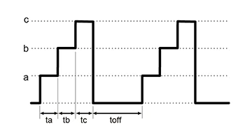
ta, tb, tc and toff can be set respectively in 0.0s, 1.0s to 99.9h.
B. Ramp
It enables to make ramp action up to the set voltage or current (or from the set voltage or current to 0 V or 0 A). It is useful to like to increase/decrease voltage or current slowly.
It helps sensitive electrical load not to get damaged by overshoot.
* As for ramp operation, you can select "Both of set voltage and current", "Voltage setting only", or "current setting only".
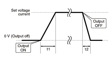
t1 and t2 can be set respectively in 0.0s, 0.1s to 999s.
C. Pulse + Ramp
It is also possible to use pulse combined with ramp action.
If a multi-set function is combined with the too, it is able to make pulse action by using voltage or current set on memory a, b, and c. Not only continuous operation, but also it is possible to specify the times.
It is useful in various aspects as it is possible to increase/decrease voltage or current slowly up to three set values.
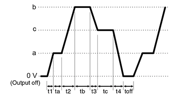
Range of 0.0s, 0.1s to 999s for t1 to t4 and range of 0.0s, 1.0s to 99.9h for ta to tc and toff can be set respectively.
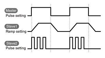
D. Master Follow (Tracking)
With the function, the slave units follow the output signals at pulse and ramp actions in master/slave mode. It is useful for the slave units to output with different conditions from the master unit.
* The master follow function is only available with the standard interface.
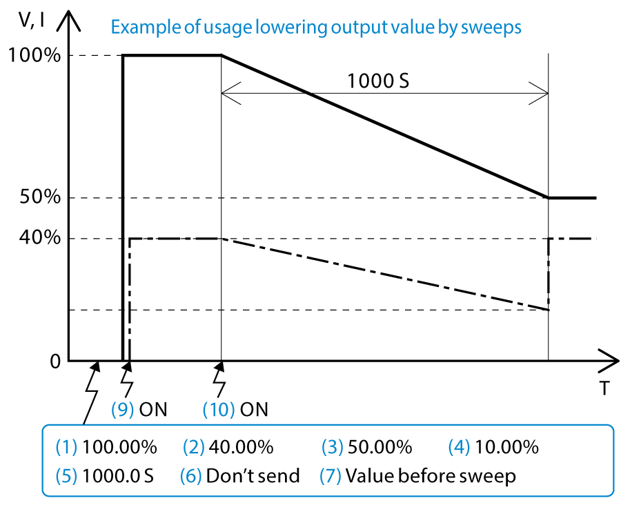
(2) Sweep Control Programming
Easy programming of sweep operation!
With the -LDe option, the available sweep commands are adapted by setting the arrival time and arrival conditions (voltage/current). Since there is no need to set commands that are repeated step by step, it is easier to create new programs and change conditions, saving a great deal of operation time. It also contributes to securing time for development, research, etc.
For details, download the datasheet below.
External Analog Control
- External output ON/OFF
- Output can be turned ON/OFF by relay or TTL signal. Logic of OUTPUT can be made reverse.
- Remote/Local change
- As for the output voltage control, output current control, overvoltage protection, and overcurrent protection, the remote/local mode can be individually switched by relay or TTL signal.
- Output monitor
- (Voltage, Current)
- Output control
- (Voltage, Current, Overvoltage protection, Overcurrent protection)
- Status output
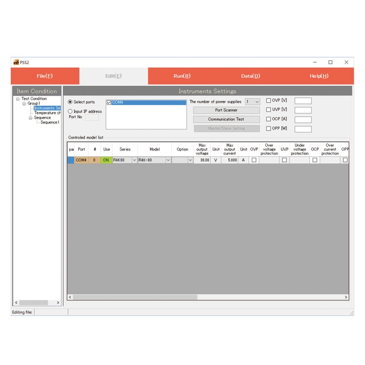
Digital Interface
Enable digit control via LAN/USB/RS-232C/RS-485/GPIB as well as one control with Master/Slave.
To use the digital interface, you need to prepare a digital interface adapter separately. For details, click here.
When a noisy environment is presumed, the following -LGob option (optical interface) is required.
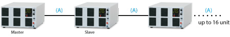
Master/Slave
Master unit can control multiple units connected as slaves. Please refer to page 05 as for “D. Master Follow”, page 04 as for “Delayed Trigger Function” and “Dual Tracking, Multiple Outputs”.
Example of Connection and Operation
Using the same multiple units of the RK series, the output voltage and output current can be increased by connecting the outputs in series or parallel.
Control must be set on each individual unit. Do not connect together COMMON of 2 units or more as the COMMON of connector for external input and output control (TB1) is connected with output.
Series operation
The total output voltage is up to 250 V. The output voltage exceeding 250 V is unavailable in a series connection. The output current will be the smallest value.
Parallel operation
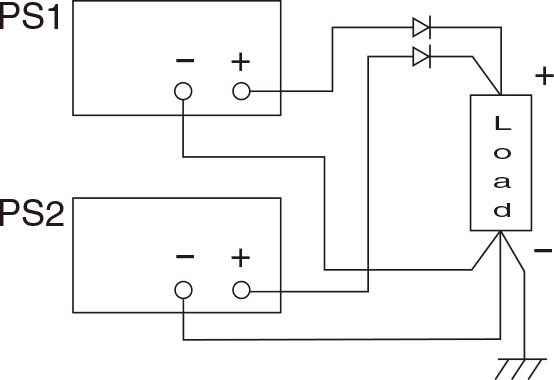
Use the same value for voltage setting in parallel connection. The output current is the sum of each current. In order to prevent damage, set the OVP level of all the power supplies to the maximum.
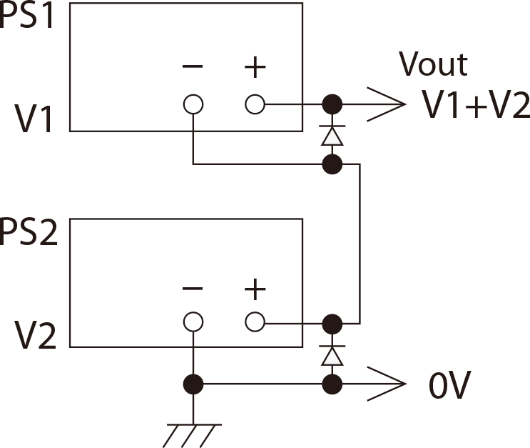
Split operation
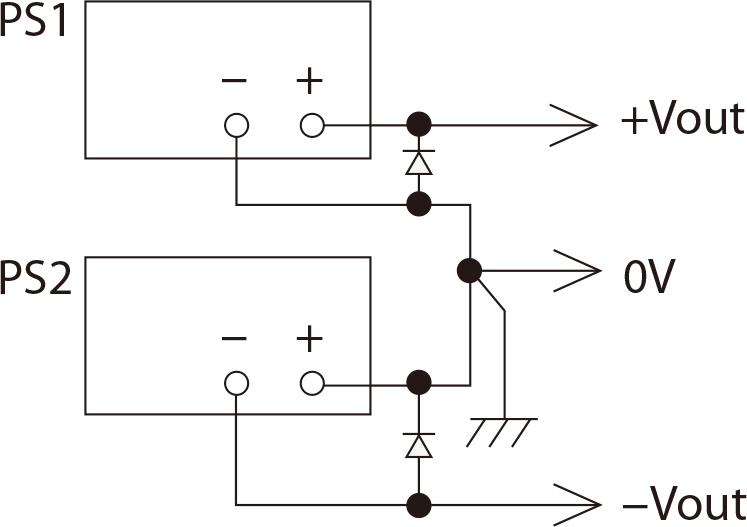
+output and –output are available. With the output voltage exceeding 250 V, the split operation is not available.
Specifications
Options
- -LCe
Corresponding to CE marking *1
- -LCk
CC-Link interface board *1 NEW
-
CC-Link master unit such as PLC can control power supplies with CC-Link compatible with CC-Link ver1.10, possible to operate as CC-Link device station. One unit occupies 2 stations, a maximum of 32 units can be controllable. Please refer to the CC-Link association web for CC-Link details.
Multiple units can be simultaneously controllable by direct, Hub, or daisy chain connection.
- -LDe
Pulse/Ramp sequence, Master follow function
-
go to Pulse/Ramp sequence, Master follow function (-LDe option)
- -LEt
LAN interface board *1 *2 *3
-
Enable digital control via LAN
HUB shall be required between RK series and your computer when control multiple RK via LAN.If this option is taken, CE certification becomes void.
- LGob
Optical interface board *2 *3
-
With optical communication, isolation control is performed. As complete isolation is performed by means of optical fiber, this enables advanced prevention of erroneous operations involved with transient phenomenon caused by surges, inductive lightning, external noise, etc.
To use the optical interface, you need to prepare an optical interface. For details, click here.
- -LGob: Optical interface board + optical cable 2 meters
- -LGob(Fc5): Optical interface board + optical cable 5 meters
- -LGob(Fc10): Optical interface board + optical cable 10 meters
- -LGob(Fc20): Optical interface board + optical cable 20 meters
- -LGob(Fc40): Optical interface board + optical cable 40 meters
Select the optional optical interface board (-LGob) when using this DC power supply under the following conditions.
- Noisy environment including factories (Example: Motors or coils are used near power supplies and loads).
- Using with high voltage floating (more than 250 V)
- Installation distance of 2 meters or more between the DC power supply and a controller such as a computer, laptop, or Programmable Logic Controller (PLC).
- -LIc
Output current accumulation function *4
-
Accumulate the output current and display its value (up to 100 Ah). The accumulated value is stored even when output is off. Because, the accumulated value which stop the output can be set preliminarily, it is very suitable to the application such as controlling plating solution.
- -LUs1
USB interface board *2 *3
-
Enable digital control via USB
When controlling several RK series DC power supplies via USB, a USB hub will be required between the computer and DC power supplies.
Corresponding OS: Microsoft Windows XP/Vista/7/8/8.1/10
All can correspond to both the 32-bit version and the 64-bit version.(Microsoft and Windows are registered trademarks of Microsoft Corporation.)
- -LZ
The handle for carrying *1
-
It can attach with all the models. (Height will increase by 8 mm.)
If this option is taken, CE certification becomes void.
- -L(Mc0.5), -L(Mc0.15)
Communication cable extension *2
-
The length of CO-M cable will be 0.5-meter long 0.15-meter long. (You can choose only either.)
- -L(SCPI)
SCPI command
-
Enable control via SCPI command.
- Please ask to our sales office about the update status of the CE marking acquisition. -LCe option can not be selected with -LCk, -LMi, -LEt or -LZ option.
- These options cannot be selected together. Only one of each can be selected.
- Please see the CO series datasheet for details of digital interface function.
- Please consider the location of usage. Environment humid and corrosive gas occurs typified by plating line can cause failure.
How to Order
When ordering, add Option No to Model No.
Example:RK30-27-LCeDeGob(Fc5)(SCPI), RK650-1.8-LDeZ(Mc0.5)(SCPI)
Accessories
Adapter for digital interface (sold separately)
To use the digital interface, you need to prepare a digital interface adapter separately.
The following interface adapters are available according to the communication method of your controller port.
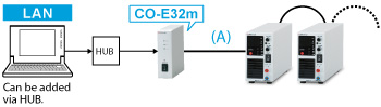
Adapter for LAN: CO-E32m
Total 16 units can be connected to one CO-E32m.
LAN cable is not provided.
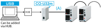
Adapter for USB: CO-U32m
Total 16 units can be connected to one CO-U32m.
USB cable is not provided.
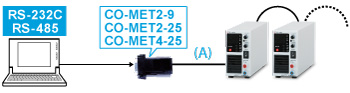
Adapter for RS-232C (9 pin): CO-MET2-9
Adapter for RS-232C (25 pin): CO-MET2-25
Adapter for RS-485 (25 pin): CO-MET4-25
[Dsub⇔Modular jack] Total 16 units can be connected.
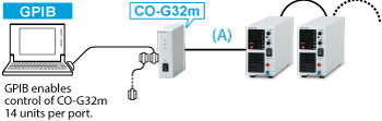
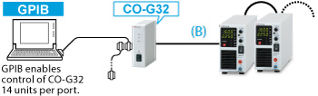
Adapter for GPIB: CO-G32m
Total 16 units can be connected to one CO-G32m.
GPIB cable is not provided.
A two-meter cable is provided in each unit without an interface option.
If you need a longer cable, please consult with our sales staff.
Optical isolation adapter (sold separately)
To use the digital interface, you need to prepare a digital interface adapter separately.
The following interface adapters are available according to the communication method of your controller port.
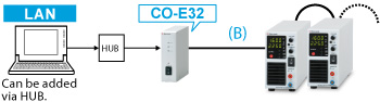
Adapter for LAN: CO-E32
Total 32 units can be connected to one CO-E32.
LAN cable is not provided.
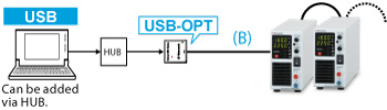
Adapter for USB: USB-OPT
Total 32 units can be connected to one USB-OPT.
USB cable is not provided.
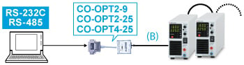
Adapter for RS-232C (9 pin): CO-OPT2-9
Adapter for RS-232C (25 pin): CO-OPT2-25
Adapter for RS-485 (25 pin): CO-OPT4-25
Total 32 units can be connected.
Adapter for GPIB: CO-G32
Total 32 units can be connected to one CO-G32.
GPIB cable is not provided.
As of models with -LGob option, a two-meter cable is provided in each unit.
If you need a longer cable, please consult with our sales staff.
Ac Input Cables
| [Standard] 400 W Models |
CABLE TYPE1 |  |
 |
125 V / 10 A | 2.5 meters Fixed length |
|---|---|---|---|---|---|
| [Standard] 800 W Models |
CABLE TYPE8 | |
|
125 V / 125 A | 2.5 meters Fixed length |
| [Standard] RK1200 W Models |
CABLE TYPE5 |  |
 |
300 V / 25 A | 2.5 meters |
| [Sold separately] 400 W and 800 W Models |
CABLE TYPE3 | |
 |
250 V / 10 A | 2.5 meters Fixed length |
| [Sold separately] 400 W and 800 W Models |
CABLE TYPE4 | |
 |
250 V / 10 A | 2.5 meters Fixed length |
| [Sold separately] 400 W and 800 W Models |
CABLE TYPE13 | |
 |
250 V / 15 A | 2.5 meters |
Please use the AC cable suitable for use environment and the area. CABLE TYPE 3 and 4 correspond to CE marking.
Dimensions
Download
If you are unable to download a file
Please try the following solution.
- Please press Ctrl+F5 to clear the cache of your web browser and try again.
- Please restart your web browser and log in again to try again.
- Please change your web browser to another browser and try again.
- Restart the computer and try again.
- Please try again on a different computer.
-
RK series Datasheet
Date: 2023-07-10 rev.21
PDF (2,111 KB)
-
DC POWER SUPPLIES SELECTION GUIDE
Date: 2023-12-06 rev.00
PDF (1,202 KB)

-
How to Use DC Power Supplies
Date: 2024-03-05 rev. 08
PDF (1,467 KB)

-
RK/REK/REKJ series Basic Instruction Manual
Date: 2022-7-8 rev.0.5
PDF (445 KB)
-
RK/REK/REKJ series Instruction Manual
Date: 2022-6-22 rev.2.0
PDF (2,942 KB)
-
RK series USB Driver
Date: 2023-08-23 rev1.7.5
ZIP (6,617 KB)
-
RK/REK/R4G series USB Driver (LMi option guide)
Date: 2020-07-02 rev0.0
PDF (152 KB)
The account registration is necessary for downloading
-
RK series Datasheet
Date: 2023-07-10 rev.21
PDF (2,111 KB)
-
DC POWER SUPPLIES SELECTION GUIDE
Date: 2023-12-06 rev.00
PDF (1,202 KB)
-
How to Use DC Power Supplies
Date: 2024-03-05 rev. 08
PDF (1,467 KB)
-
RK/REK/REKJ series Basic Instruction Manual
Date: 2022-7-8 rev.0.5
PDF (445 KB)
-
RK/REK/REKJ series Instruction Manual
Date: 2022-6-22 rev.2.0
PDF (2,942 KB)
-
RK series USB Driver
Date: 2023-08-23 rev1.7.5
ZIP (6,617 KB)
-
RK/REK/R4G series USB Driver (LMi option guide)
Date: 2020-07-02 rev0.0
PDF (152 KB)
In this website, we provide only the latest version of information including instruction manuals as of our products. Therefore, the newest versions of manuals on the website might be not same as the ones of products you purchased in the past.