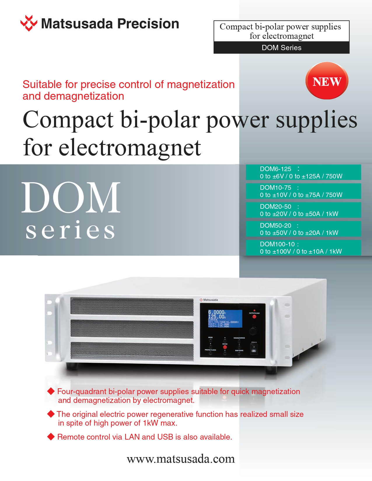
Suitable for precise control of magnetization and demagnetization by electromagnet!
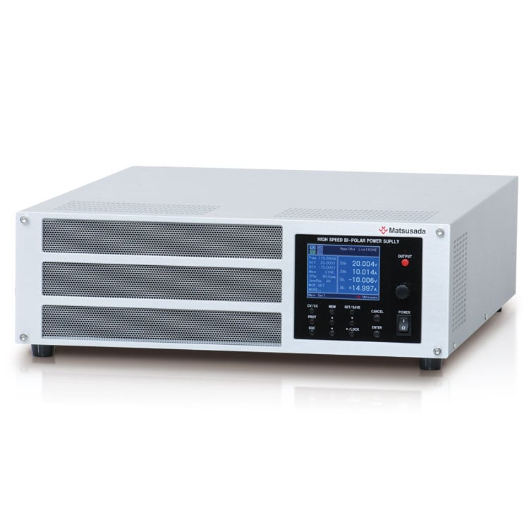
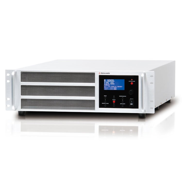
DOM series is a four-quadrant bipolar power supply which succeeded in miniaturization by high-efficiency switching amplifier method and electric power regenerative function.
It can also realize smooth demagnetization, thanks to a high current which is required in magnetization of the electromagnet and four-quadrant operation that can perform both "source" and "sink" of electric power.
By the simple operation on the front panel, the setting of output voltage/current and the outputting safely are available.
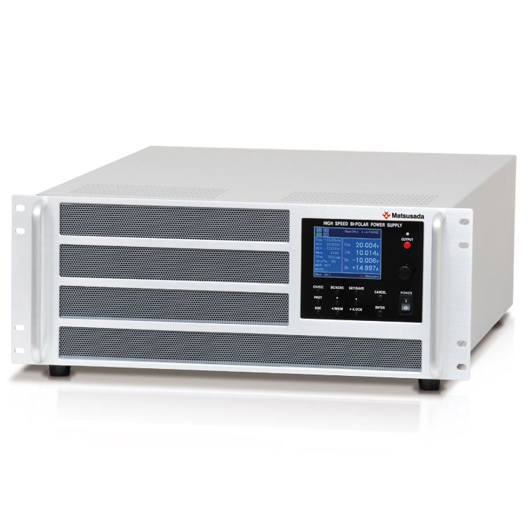
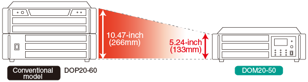
- Though the new model is the same 1 kW
- output class, height becomes half
Features and Benefits
- Source and sink of current of ±125 A maximum are available in spite of the compact size of height 3 U.
- DOM can control electromagnet quickly and precisely because of four-quadrant operation.
- Utilizing electricity effectively* and reducing generation of heat are available because of electric power regenerative function.
- Low ripple, excellent stability and useful protection realize high performance and safer safety.
* It is designed on the assumption that all regenerated electrical power is consumed on the premises.
Applications
Control of electromagnet, testing for in-vehicle electrical components and various motors, evaluation test for solar panel and film formation (electroplating)
There is a dedicated power supply suitable for such use, so please feel free to refer.
Models
Available in the near future. For details, please ask our sales office.
| Model | Output | Frequency bandwidth (-3 dB) | ||
|---|---|---|---|---|
| Voltage [V] (rms) | Current [A] (rms) | Power [kW] | ||
| DOM6-125 | 0 to ±6 V (0 to ±4.2 V) |
0 to ±125 A (0 to ±87.5 A) |
0.75 kW |
DC to 1 kHz (at low amplitude) |
| DOM10-75 | 0 to ±10 V (0 to ±7 V) |
0 to ±75 A (0 to ±52.5 A) |
0.75 kW | |
| DOM20-50 | 0 to ±20 V (0 to ±14 V) |
0 to ±50 A (0 to ±35 A) |
1 kW | |
| DOM50-20 | 0 to ±50 V (0 to ±35 V) |
0 to ±20 A (0 to ±14 A) |
1 kW | |
| DOM100-10 | 0 to ±100 V (0 to ±70 V) |
0 to ±10 A (0 to ±7 A) |
1 kW | |
Specifications
Options
-LGob: Optical Interface Board
- -LGob: Optical interface board + optical cable 2 meters
- -LGob(Fc5): Optical interface board + optical cable 5 meters
- -LGob(Fc10): Optical interface board + optical cable 10 meters
- -LGob(Fc20): Optical interface board + optical cable 20 meters
- -LGob(Fc40): Optical interface board + optical cable 40 meters
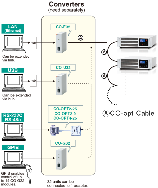
Isolated control is realized via optical communication.
It is possible to prevent malfunction such as transient phenomenon by surge, lightning induction and exogenous noise.
Output ON/OFF, setting the value of output voltage/current, switching CV mode and CC mode
(A converter is required separately. Please ask our sales representative.)
- Select the optional optical interface board (-LGob) when using this bipolar power supply under the following conditions.
-
- Noisy environment including factories (Example: Motors or coils are used near power supplies and loads).
- Using with high voltage floating (more than 250 V).
- Installation distance of 2 meters or more between the bipolar power supply and a controller such as a computer, laptop, or Programmable Logic Controller (PLC).
How to Order
To order, please add the above following option mark to the model number.- Example:
- DOM100-10-LGob
- DOM6-125-LGob(Fc40)
- (Alphabetical and input voltage order)
Dimensions
Tech Notes
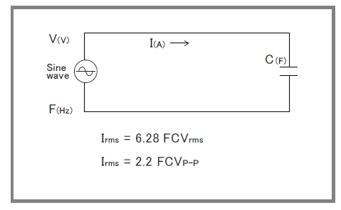
Capacitive Load
When a capacitive load is more than 100 pF (including a stray capacitance of output wire), the resonance in the output may occur. In that case, install 100-ohm (@0.1 μF) to 1000-ohm (@1000 pF) of high voltage resistance in the output in series. Please note that the frequency band will be limited as the formula written in the right figure when an amplifier is used with a capacitive load.
In addition, when an amplifier is used for the use such as a corona discharge, the current which is higher than rating will flow and it will affect the amplifier badly. In this case, as well as the time to use an amplifier with a capacitive load, please install the output resistance and limit the current.
* Please avoid continuous inputting of high frequency signal which reduces output frequency of an amplifier. An amplifier will be broken because of increase of internal loss.
Download
If you are unable to download a file
Please try the following solution.
- Please press Ctrl+F5 to clear the cache of your web browser and try again.
- Please restart your web browser and log in again to try again.
- Please change your web browser to another browser and try again.
- Restart the computer and try again.
- Please try again on a different computer.
-
DOM series Datasheet
PDF(704KB)
The account registration is necessary for downloading
-
DOM series Datasheet
PDF(704KB)
In this website, we provide only the latest version of information including instruction manuals as of our products. Therefore, the newest versions of manuals on the website might be not same as the ones of products you purchased in the past.