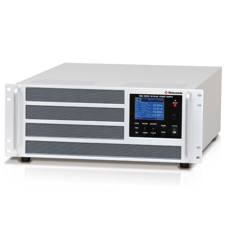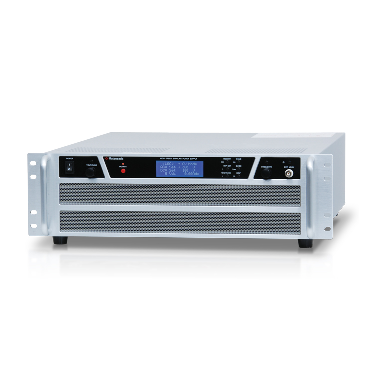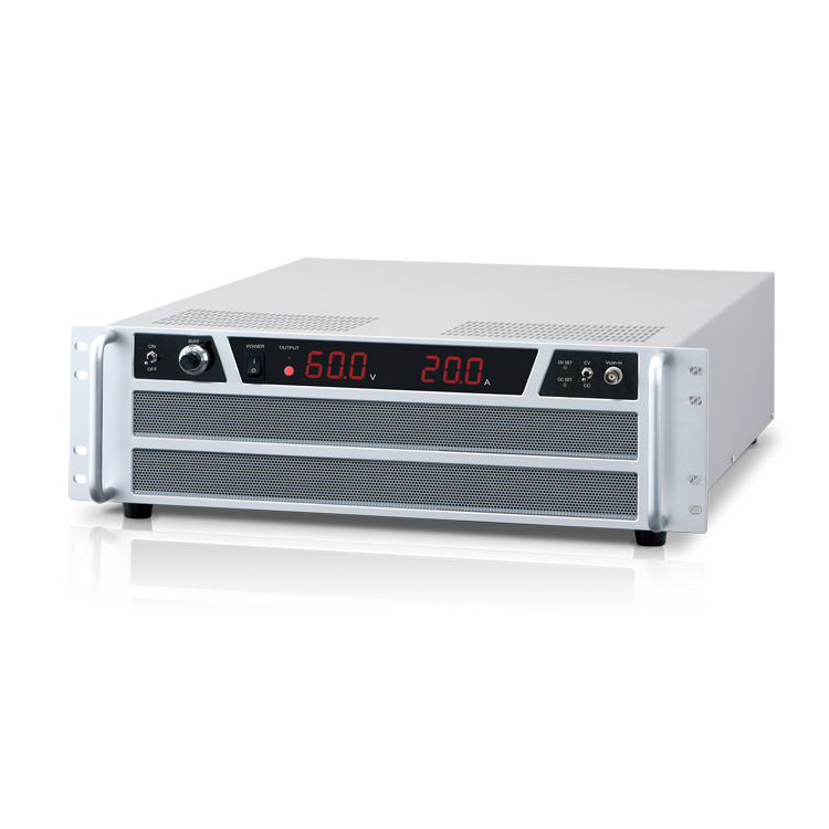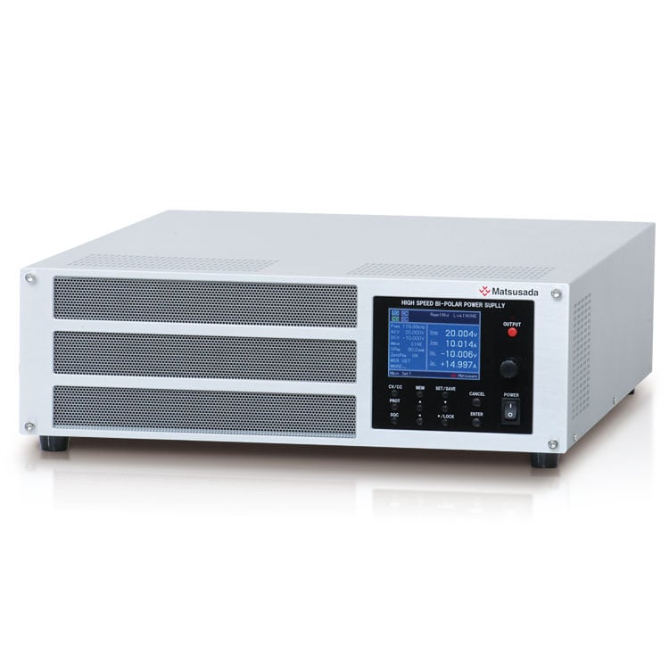
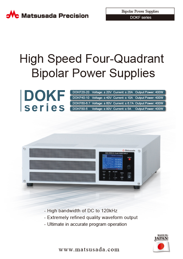
HIGH SPEED FOUR-QUADRANT BIPOLAR POWER SUPPLIES
- Voltage range: ±20V to ±80V
- Current: ±5A to ±20A
- Power: 400W
- Ultimate in accurate program operation
FOUR-QUADRANT BIPOLAR POWER SUPPLIES ARE DEVELOPED UP TO THE FOLLOWING.
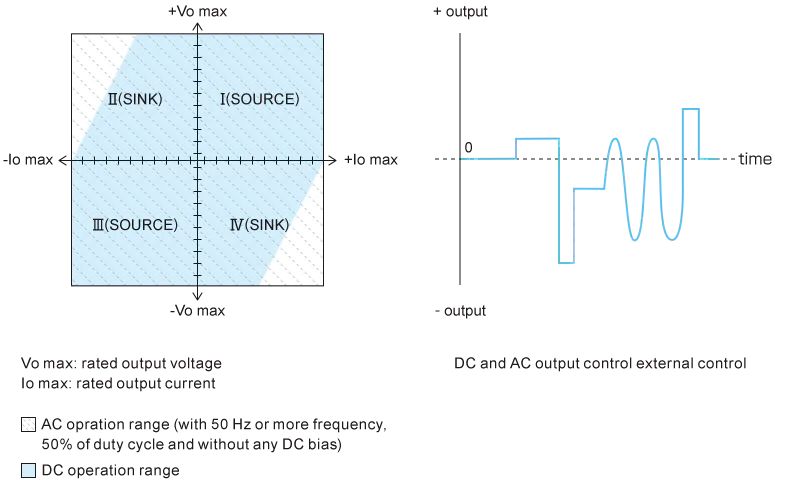
DOKF series are four-quadrant power supplies possible to source and sink current.
They can be applied widely according to the usage from transient response test to various product tests as they realize high speed response of DC to 120 kHz (at constant voltage mode) and can generate basic waves such as sine wave, rectangular wave and programmed waves by embedded function generator.
And, as they provide also the high resolution sequence function as standard, you can program output patterns in detail. Moreover, as their generation of wave and setting sequence can be made all with the simplified operation on the front panel, you can make full use of various functions easily.
FEATURES AND BENEFITS
- Superior visibility and operability by using color liquid crystal display (LCD).
- High bandwidth of DC to 120kHz.
- Four-quadrant behavior able to source and sink current.
- It is possible to generate non-distortional wave such as sine wave, rectangular wave.
- It is possible to set and operate high-performance sequences in 1024 steps.
- There are 2 modes of DC and AC + DC and each of them can be set individually.
- 2 mode operation of CV (constant voltage) and CV (constant current) are applicable.
- Synchronous operation (synchronized clock) of frequency accuracy and up to three power supplies in parallel (synchronized trigger) available.
- GPIB, USB and RS-232C interface are equipped as standard.
- It is possible to output voltage/current in 16 bits and customized waves of resolution of 1024 in one cycle. (optional control software)
- Highly accurate program operation.
- Arbitary waveform is to output in high quality.
- Extremely refined quality waveform output.
APPLICATIONS
- To Drive capacitive loads such as a capacitor.
- To Drive inductive loads such as coils and transformers.
- Tests of various motors.
- Testing of power inverters such as for solar panels.
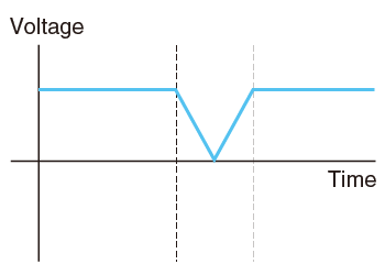
- Voltage fluctuation tests for automotive electrical components.
Note: We have not designed this product to be charge and discharge batteries.
For battery charging and discharging applications, please refer to the Battery Cycle Tester product page.
OPERATION RANGE
Models
Please consult with us for specifications other than the below.
| Model | Output | Frequency Bandwidth (-3 dB) | |||
|---|---|---|---|---|---|
| Voltage | Current | Power | CV mode | CC mode | |
| DOKF20-20 | ±20 V | ±20 A | 400 W | DC to 120 kHz | DC to 60 kHz |
| DOKF40-10 | ±40 V | ±10 A | |||
| DOKF60-6.7 * | ±60 V | ±6.7 A | DC to 50 kHz | ||
| DOKF80-5 * | ±80 V | ±5 A | |||
* They are available in the near future. Please contact our sales staff for detail.
Functions
Basic waveform generation function
DOKF is equipped with a built in function generator that produces basic waves such as sine, rectangular and triangle waves.
Frequency range can be set between 0.01 Hz and 120 kHz. Easy adjustments/edition of amplitude, start phase (for sine wave), phase shift (for sine wave), and duty ratio (for rectangular/triange wave) are possible. DOKF has special feature of “soft start” and “soft stop” which enable to program initial rise and fall characteristics of the output.
Start phase
Soft start
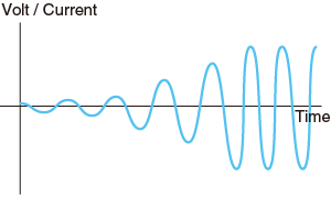
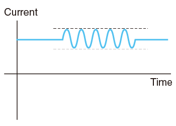
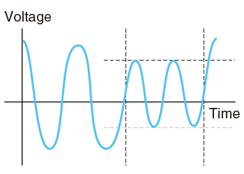
AC Volt/current sweep, frequency sweep
Soft stop
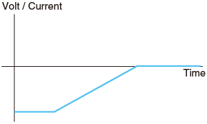
DC Volt/current ramp
Applications
Power activation test, Various start-up tests of motor, etc, Fluctuation test of wave shape and so on.
Sequence functions
DOKF is equipped with sequence function that can program parameters such as step time, step amplitude ramp, DC voltage and current ramping, AC voltage and current ramping, frequency sweep, AC superposition, step jump, and jump times. These useful functions help to program the desired waves in very flexible manner, resulting to support efficient laboratory and research works.
Complex sequence can be created easily with the intelligible display.
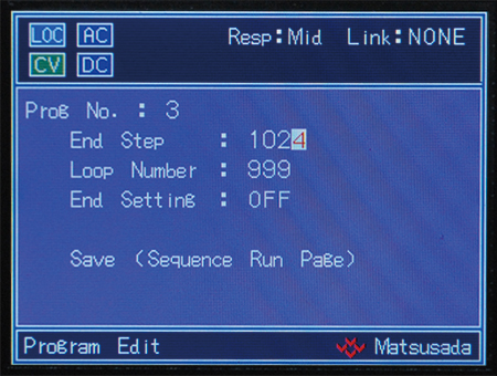
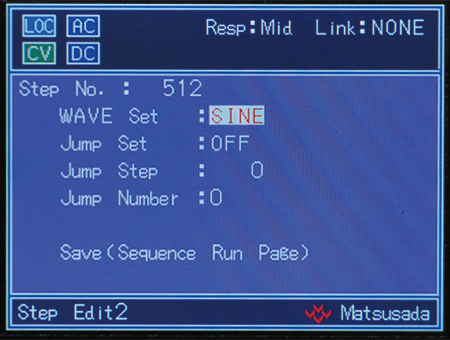
- Step time 0.1 ms to 1000 h (resolution of 0.1 ms)
- Maximum 1024 steps per program.
- Maximum 64 programs can be stored in memory for each CC/CV operation
- Program repeat can be set by “endless repeat” or “1 time to 10000 times”
- Multiple programs can be converted to activate
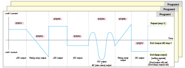
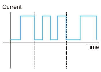
Sequence functions help to create complicated waves like the below to be simply and easily edited.
Applications
Test for motors, Pulse power supply and Various evaluation.
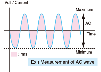
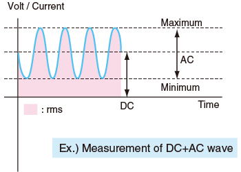
Measurement functions
DOKF is equipped with a measurement function that can measure DC value, AC RMS value, and Max/Min value, likewise, it is possible to automatically measure wide range bandwidth from DC to 120 kHz. There are 4 parameters which are simultaneously displayable, each of these parameters are individually programmable. As this measurement is a standard feature, no option needs to be purchased. This sophisticated feature will reduce the time for editing output waves and bring up work efficiency.
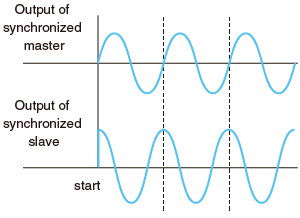
Synchronized Operation
The following DOKF operations are available for up to three units.
Synchronous trigger
Through a single operation of the master unit, it is possible to match the output timing of ON/OFF in one or two slave units. In turning the output on, the output starting gap between the master and the slave is less than 0.5 μs
*To use this function, please purchase “Dedicated cable for synchronous trigger” of 2 meters separately.
Synchronous clock
By providing the clock input of 10 MHz, the individual difference between the oscillators installed on each unit is removed (In the case of this, there are a few ppm up to several tens ppm in general). What is more, frequency accuracy and sequence-step time are completely unified through the operation.
Moreover, the product is also available for setting the phase shift difference for the sine wave toward each unit.
(*Please prepare the coaxial cable on both ends of BNC connectors which is not included but required for the synchronous clock.)
*When the slave unit is required to synchronize in accordance with the waveform set by the master unit, -the LMs option must be taken (in master/slave control).
Note that the time synchronized operation is not available if using the master/slave control.
- Other functions:
- Protection function (turn-off or limit settable individually), Key lock function, Switching CV/CC, and Memory function (up to 99) are installed as standard.
Control Pannel Display
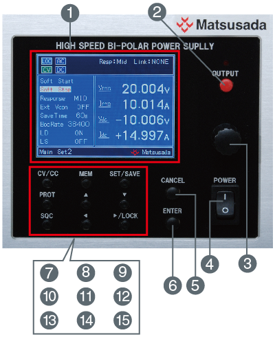
- Display: Display various settings and measurements.
- OUTPUT switch: ON/OFF for output
- Rotary encoder: Change value
- POWER switch: ON/OFF for main power
- CANCEL switch: Cancel settings
- ENTER switch: to Confirm and key in
- CV/CC switch: Switchover CV/CC mode
- MEMORY switch: Switchover memory screen
- SETTING/STORAGE switch: Make to setting change menu, store memory
- PROTECTION switch: to Switch protection setting menu
- Shift up switch: Shift up each setting items
- Shift down switch: Shift down each setting items
- SEQUENCE switch: Use for switchover of sequence screen or interrupt or restart of sequence operation
- Shifting left switch: Shift digits of settings to left
- Shifting right/LOCK switch: Shift digits of settings to right and also use the key lock function
Specifications
Options
- -LCk
-
CC-Link interface board
It enables digital remote control via the network of CC-Link.
- -LMsm, -LMss
-
Master/Slave control (parallel operation)
Maximum 3 units, including the master unit, are hooked. (“-LMsm” for the master unit and “-LMss” for slave units. Please order required number of units.
Every master unit and slave units are exclusive use. When change the combination of master/slave, they should be readjusted in our shop.)
(If you take this option, the synchronized operation is not available.)
- -LRa
-
The front panel attachable to the 19 inches rack of EIA or JIS
The front panel becomes the panel attachable to the 19 inches rack of EIA or JIS standards.
Dimension of the front panel is modified in case attached. Please consult our sales staff.
(It is impossible to support the main unit only with these brackets. Please utilize always a sole plate or angle bars to support the unit weight.)
Accessories
| Standard | CABLE TYPE8 |  |
 |
125 V / 125 A | 2.5 meters Fixed length |
|---|---|---|---|---|---|
| Sold separately | CABLE TYPE3 | |
 |
250 V / 10 A | 2.5 meters Fixed length |
| Sold separately | CABLE TYPE4 | |
 |
250 V / 10 A | 2.5 meters Fixed length |
Please use appropriate AC cable.
- DOKF-ST cable
-
Synchronized trigger cable
for one master unit and one slave unit
- DOKF-ST2 cable
-
Synchronized trigger cable
for one master unit and one slave unit
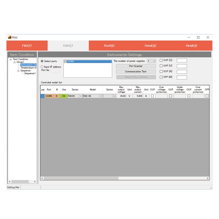
Application software for power supplies
PSS2en-DOKF
This is the dedicated software to make DOKF series to activate sequence operation with simplified setting. Of course sequence operation of high speed and large storage capacity in the power supply, it can generate and output optional wave from the power supply.
(USB or RS-232C)
For details, refer to PSS2en page.

Dimensions
Tech Notes
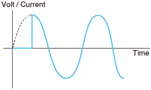
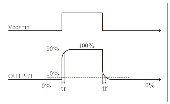
Characteristics of amplifier
Rise time
(step time): responsiveness may be expressed with rise time. (see right figure)
Rise time for amplifiers in fc (Hz) of response time (= frequency band) is calculated with the following equation generally.
"tr ≒ 0.35/fc"
Decay time tf is equal to tr.
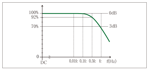
Frequency bandwidth
: to 120 kHz, tr = tf ≒ 2.9 μs
: to 60 kHz, tr = tf ≒ 5.8 μs
Response speed
When an accurate output wave is required, please select an amplifier in a sufficiently higher frequency band than the applied one. Generally, a speedy frequency band of 3 times to 5 times of applied frequency for a sine wave and 10 times for a rectangular wave is required. If the frequency band is in lacking, as not only is output oscillation reduced but also the phase difference of input and output becomes larger, consideration to apply it monitoring output wave is required.
For capacitive loads
In the case of capacitive load, oscillation may be caused. If so, please insert a power resistance to the output in the series.
And, in capacitive load, please attend that the frequency band is limited by the resistance and capacitance inserted in series.
For inductive loads
At CC mode, oscillation may be caused by the inductance of inductive loads.
If so, please connect the C-R straight circuit between output terminals so as not to cause oscillation.
Download
If you are unable to download a file
Please try the following solution.
- Please press Ctrl+F5 to clear the cache of your web browser and try again.
- Please restart your web browser and log in again to try again.
- Please change your web browser to another browser and try again.
- Restart the computer and try again.
- Please try again on a different computer.
-
DOKF series Datasheet
Date: 2023-07-26 rev.13
PDF (2,600 KB)
-
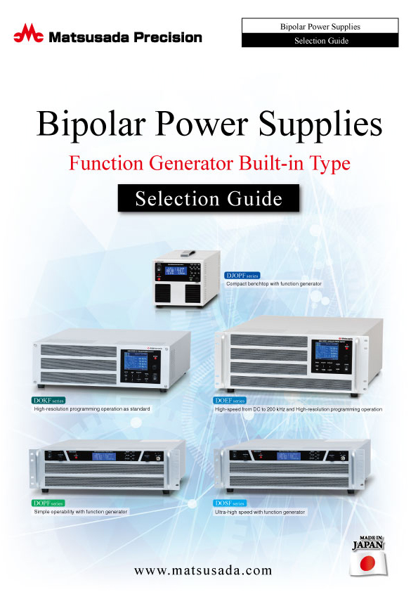
Bipolar Power Supplies with Function Generator
Date: 2023-07-26 rev.03
PDF (6,666 KB)
-
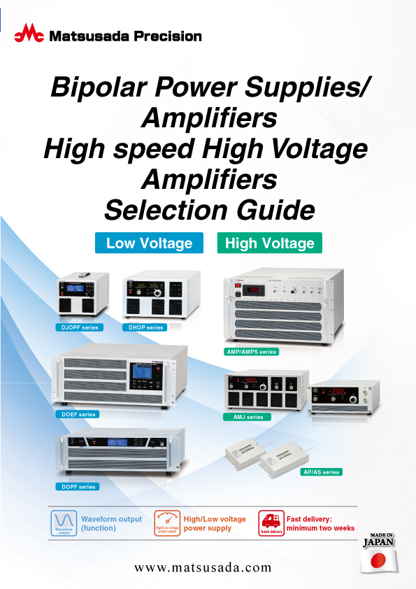
Bipolar Power Supplies/Amplifiers Selection Guide
Date: 2023-10-17 rev.03
PDF (6,310 KB)

-
DOKF series Instruction Manual
Date: 2022-9-1 rev0.9
PDF (2,327 KB)
-
DOKF series Instruction Manual (Communication Interface)
Date: 2022-3-3 rev.0.6
PDF (1,430 KB)
-
DOKF series USB Driver
Date: 2023-08-23 rev1.7.5
ZIP (6,617 KB)
The account registration is necessary for downloading
-
DOKF series Datasheet
Date: 2023-07-26 rev.13
PDF (2,600 KB)
-
Bipolar Power Supplies with Function Generator
Date: 2023-07-26 rev.03
PDF (6,666 KB)
-
Bipolar Power Supplies/Amplifiers Selection Guide
Date: 2023-10-17 rev.03
PDF (6,310 KB)
-
DOKF series Instruction Manual
Date: 2022-9-1 rev0.9
PDF (2,327 KB)
-
DOKF series Instruction Manual (Communication Interface)
Date: 2022-3-3 rev.0.6
PDF (1,430 KB)
-
DOKF series USB Driver
Date: 2023-08-23 rev1.7.5
ZIP (6,617 KB)
In this website, we provide only the latest version of information including instruction manuals as of our products. Therefore, the newest versions of manuals on the website might be not same as the ones of products you purchased in the past.