Discontinued
Ultra-low ripple noise bipolar power supplies for exclusive use of the electromagnet
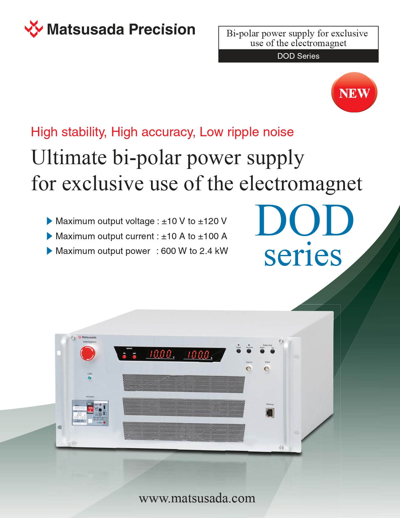
High stability, High accuracy, Low ripple noise
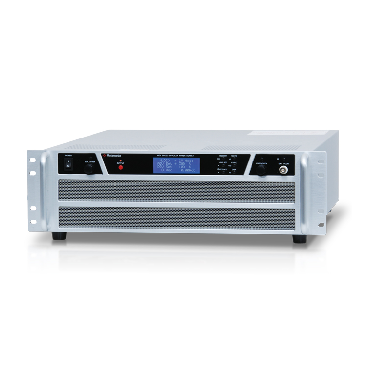
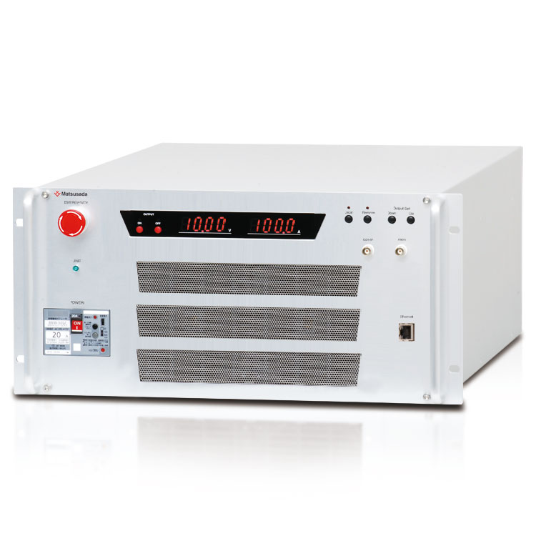
High-performance bipolar power supplies for exclusive use of the electromagnet
DOD series are the ultra-low ripple noise bipolar power supplies for the exclusive use of the electromagnet. From the wide lineup(the range of output current; ±10 A to ±100 A), You can choose the most suitable model for the characteristic of your electromagnet.
Special attention has been paid to designing the internal circuits of the power supply to be symmetrically placed, which helps reduce a great amount of common-mode noise, despite the amazing small footprint of the equipment.
DOD series is the most suitable power supply for an electromagnet as a high-stability and low noise current supply source.
Features
- Wide lineup
- You can choose the most suitable model from the wide lineup of up to ±120 V from ±10 V.
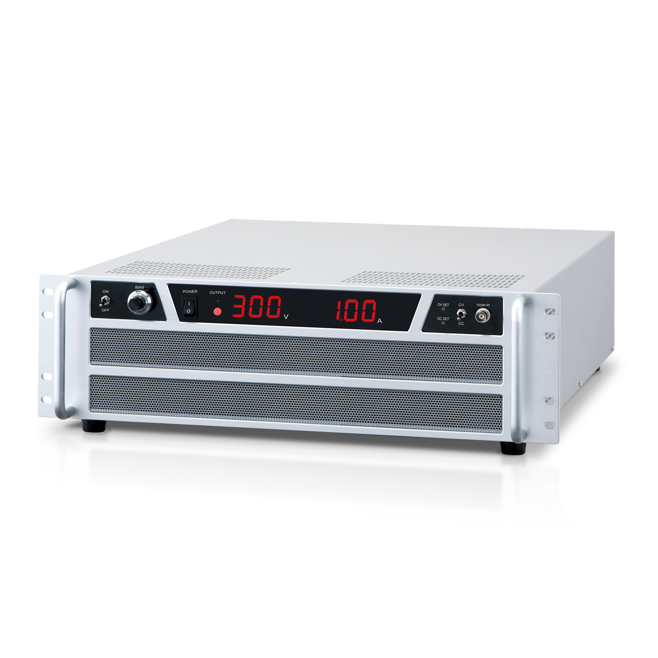
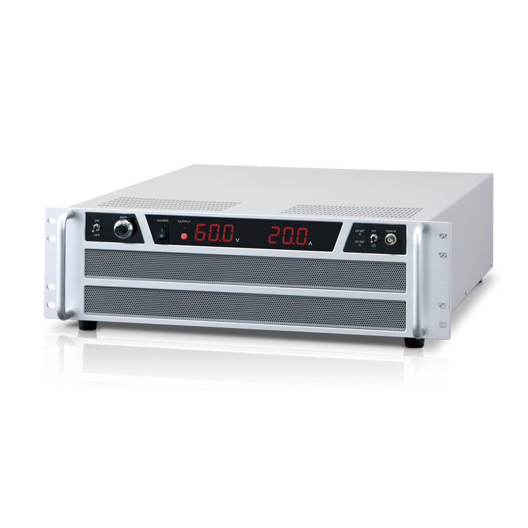
- The display of DC output voltage and current value
- DC output voltage and current value is displayed on 3.5-digit digital meter on the front panel.
- Compact and Lightweight
- DOD series is designed to pursue possible smallest footprint and lightweight, results in user's great space-saving.
- Useful protection function
- Protections such as for overvoltage, overcurrent, output short circuit, cooling fan error and power failure are standardly equipped to DOD series.
- Digital control
- Digital control via LAN (Ethernet) is available.
Applications
- Electromagnetic power supply for accelerators
Models
Please feel free to ask us about the specifications except the list below.
| Model | Output | Input | |||||
|---|---|---|---|---|---|---|---|
| Voltage [V] | Current [A] | Power [W] | Standard | -L(400V) option | |||
| Voltage | Current (@200V) | Voltage | Current (@400V) | ||||
| DOD10-100 | ±10 | ±100 | 1000 |
AC200 V to 240 V ±10% 3-phase |
6 A typ |
AC400 V ±10% 3-phase |
3 A typ |
| DOD20-30 | ±20 | ±30 | 600 | 5 A typ | |||
| DOD40-30 | ±40 | ±30 | 1200 | 6 A typ | |||
| DOD60-20 | ±60 | ±20 | 1200 | ||||
| DOD80-10 | ±80 | ±10 | 800 | ||||
| DOD120-20 | ±120 | ±20 | 2400 | 12 A typ | 6 A typ | ||
Functions
About protection function
- OVP (Overvoltage protection)
- Output voltage is limited not to exceed approx. 120% of the rated voltage in an emergency case, thus protects the load.
- OCP (Overcurrent protection)
- Output current is limited not to exceed approx. 120% of the rated current in an overload case, thus protects power supply and load.
Explanation of functions
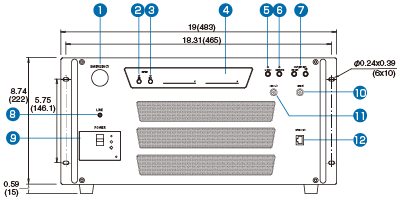
Front
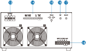
Rear
- Emergency stop button
- OUTPUT ON switch
- OUTPUT OFF switch
- Output voltage/current meter
- "Local" button
- "Remote" button (control via Ethernet)
- Button for setting output current
- LED for displaying the state of power receiving
- POWER switch
- Terminal for monitoring output current
- Icon-in terminal
- LAN (Ethernet) connector
- Output terminal
- Terminal for status signal and interlock
- Terminal for monitoring output voltage
- Terminal for monitoring preset value of output current
- Terminal 2 for monitoring output current
- AC input terminal
Specifications
Options
-L(400V)
For the change of input voltage and current.
-LTc
Temp. stability of output current; 5 ppm/℃
-LEp
Control by EPICS
(Experimental Physics and Industrial Control System)
How to order
To order, please add the above option number to the model number.[Example] DOD10-100-LEpTc (Alphabetical order)
Dimensions
Tech Notes
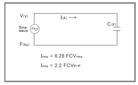
Capacitive Load
When a capacitive load is more than 100 pF (including a stray capacitance of output wire), the resonance in the output may occur. In that case, install 100-ohm (@0.1 μF) to 1000-ohm (@1000 pF) of high voltage resistance in the output in series. Please note that the frequency band will be limited as the formula written in the right figure when an amplifier is used with a capacitive load.
In addition, when an amplifier is used for the use such as a corona discharge, the current which is higher than rating will flow and it will affect the amplifier badly. In this case, as well as the time to use an amplifier with a capacitive load, please install the output resistance and limit the current.
* Please avoid continuous inputting of high frequency signal which reduces output frequency of an amplifier. An amplifier will be broken because of increase of internal loss.
Download
If you are unable to download a file
Please try the following solution.
- Please press Ctrl+F5 to clear the cache of your web browser and try again.
- Please restart your web browser and log in again to try again.
- Please change your web browser to another browser and try again.
- Restart the computer and try again.
- Please try again on a different computer.
-
DOD series Datasheet
PDF(540KB)
The account registration is necessary for downloading
-
DOD series Datasheet
PDF(540KB)
In this website, we provide only the latest version of information including instruction manuals as of our products. Therefore, the newest versions of manuals on the website might be not same as the ones of products you purchased in the past.